How to Enable LACP and Jumbo Frames - (Windows & OS X)
SANLink2 10Gb Drivers and Utility (OS X Only)
SANLink2 10G Ethernet Network Adapter Driver for Windows 64bit v20.3
SANLink2 10G BaseT/10G SFP+ Mac Driver v1.8.1
SANLink2 Utility for Mac OS X v1.04.0000.08
Table Of Contents
I. Create LACP with Default MTU 1500 - Windows
II. Enable Jumbo Frames on Windows WHQL certified driver for Windows 7 SP1 / Windows 8.1 and Windows 10. (All 64bit ONLY) MTU 9000
III. Create LACP with Default MTU 1500 - OS X
IV. Enable Jumbo Frames MTU 9000 - OS X
I. Create LACP with Default MTU 1500 - Windows
1. Make sure to identify your 10 Gb Network Ports from the SANLink2
2. Go to Change adapter settings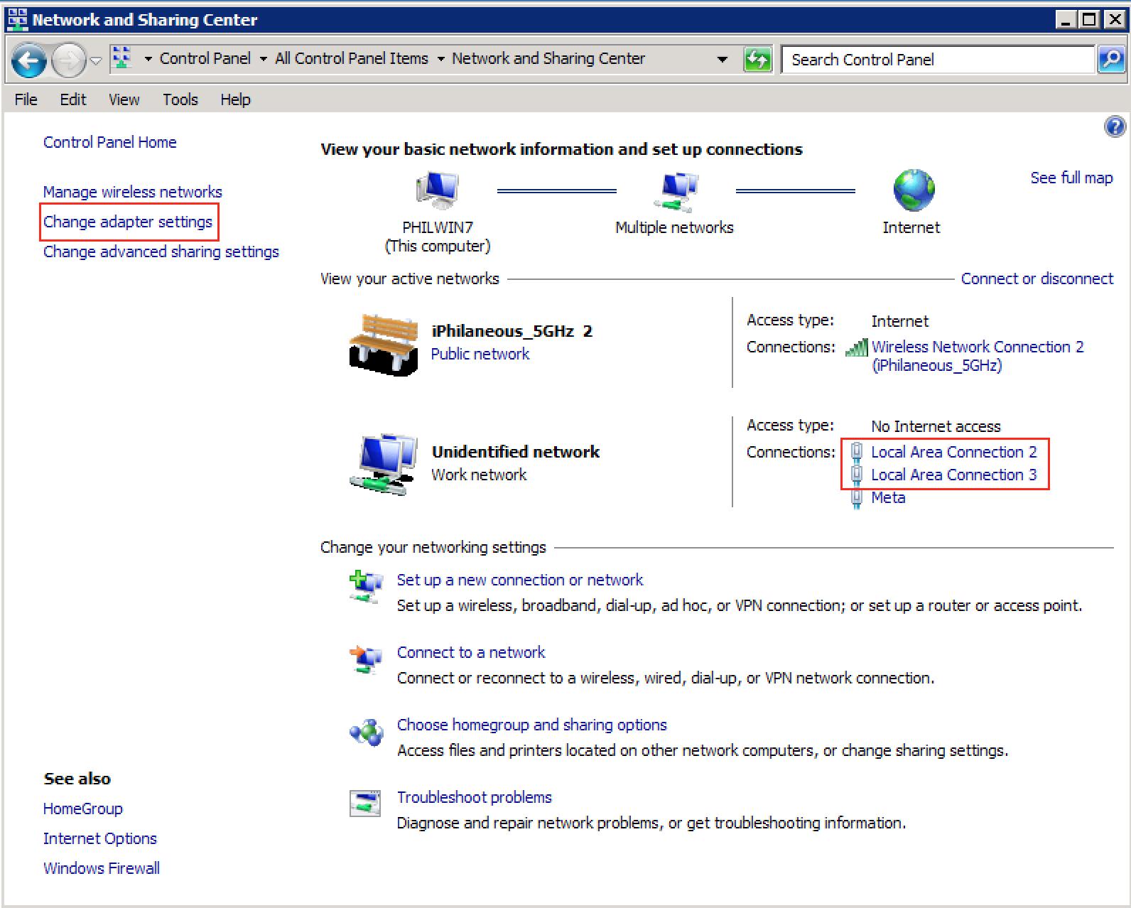
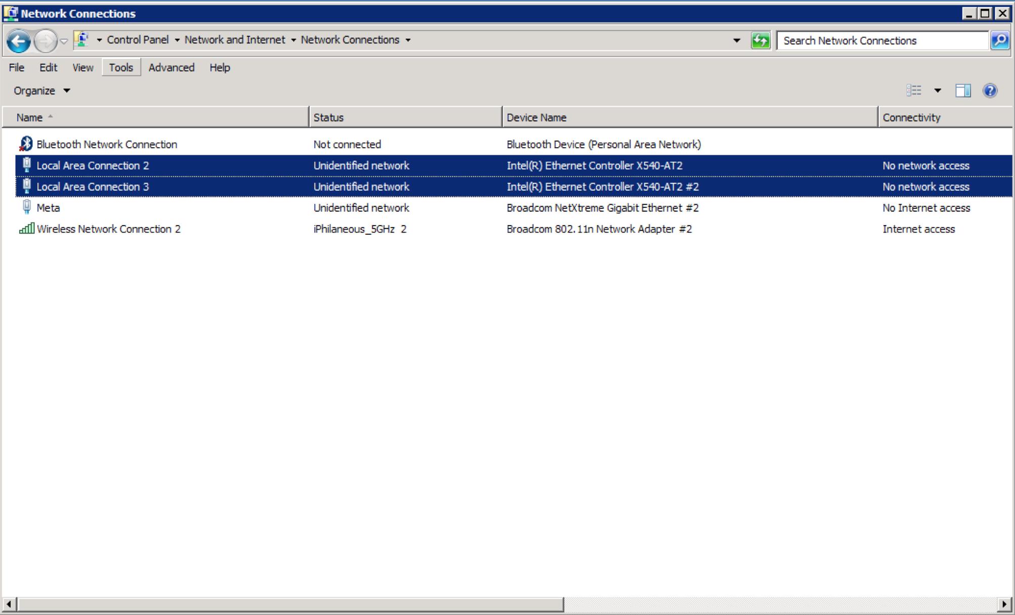
3. You can also verify the connected devices by going to My Computer > Properties > Device Manager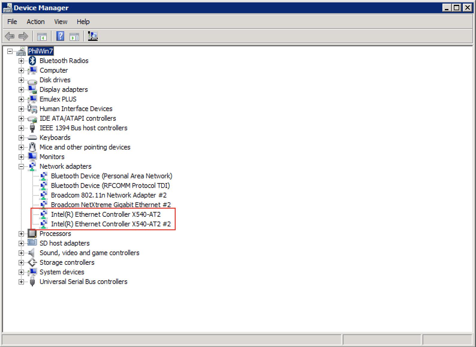
4. Locate Intel(R) Ethernet Controller X540-AT2
5. Right Click on Intel(R) Ethernet Controller X540-AT2 and select Properties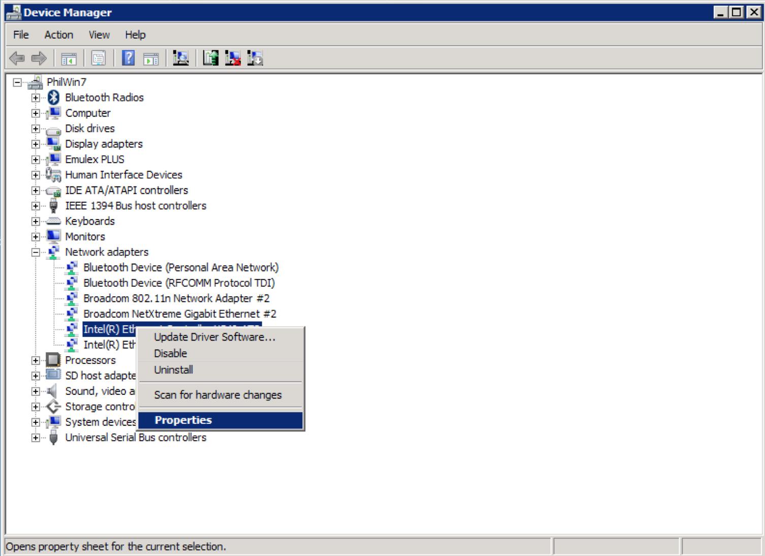
6. Navigate to the Teaming Tab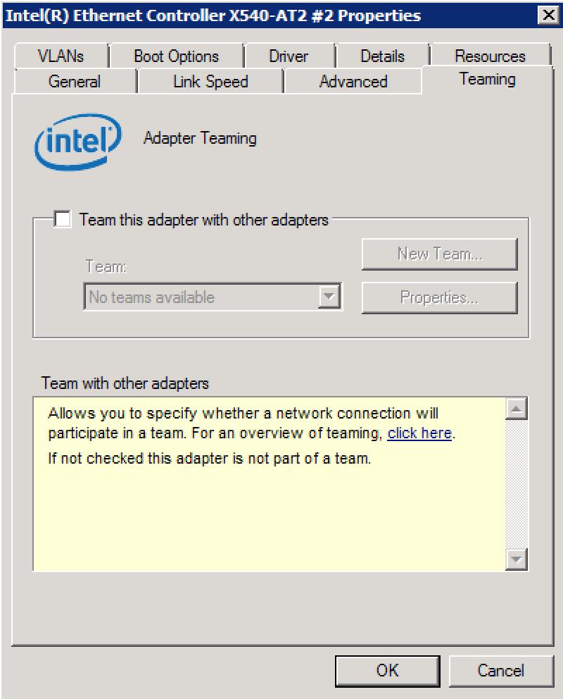
7. Select the checkbox, "Team this adapter with other adapters" and click on New Team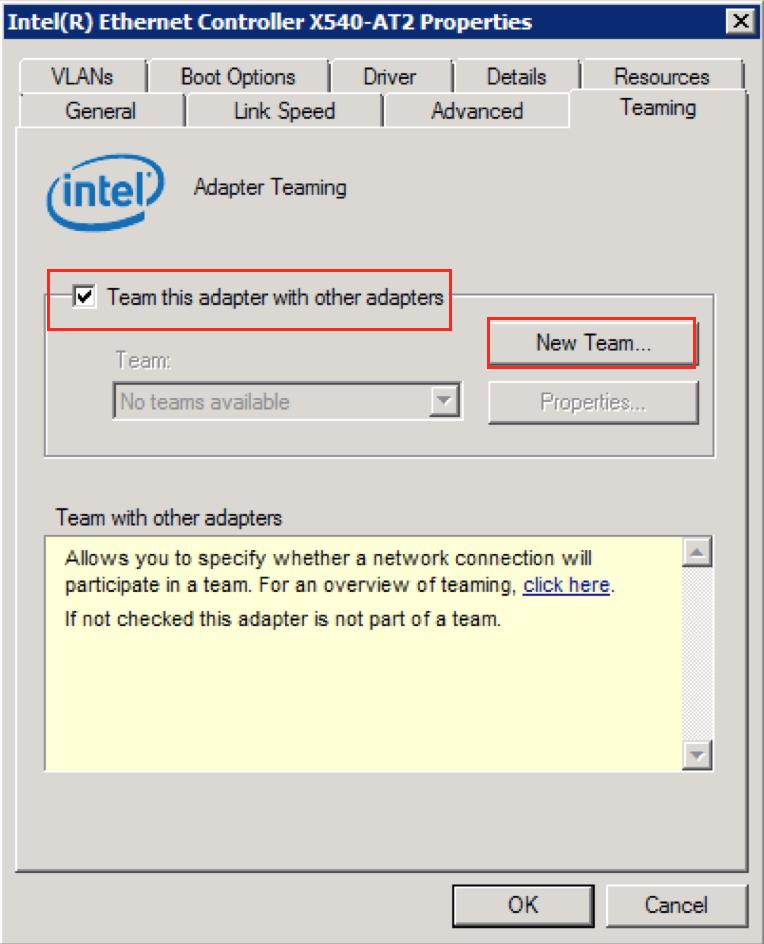
8. Specify a name for the team: LACP_Example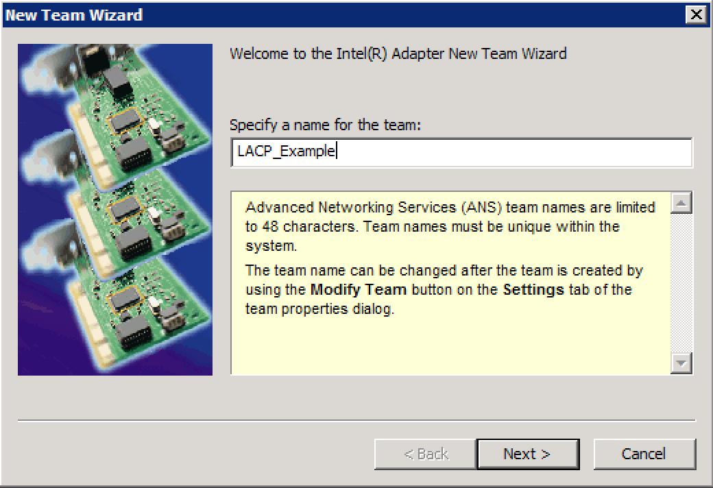
9. Click Next, and select both Intel(R) Ethernet Controller X540-AT2 and #2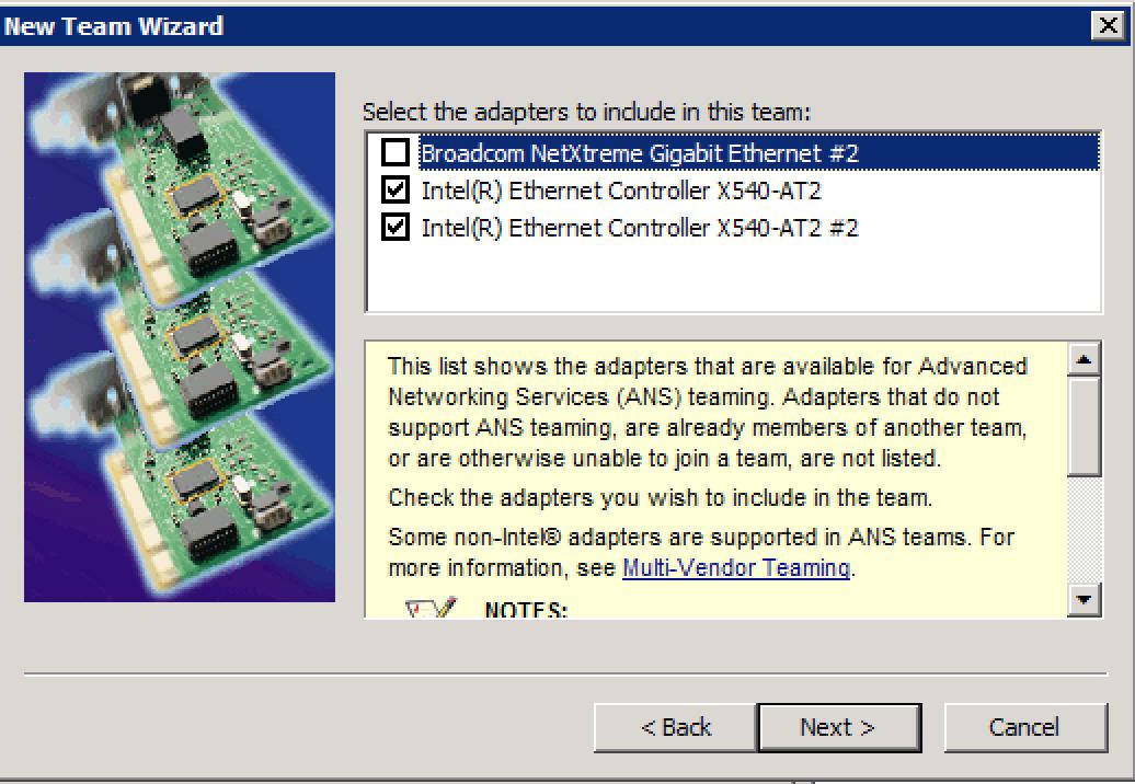
10. Select a team type: IEEE 802.3ad Dynamic Link Aggregation. (There are other options to choose from, you may select the team type that best suits yours needs)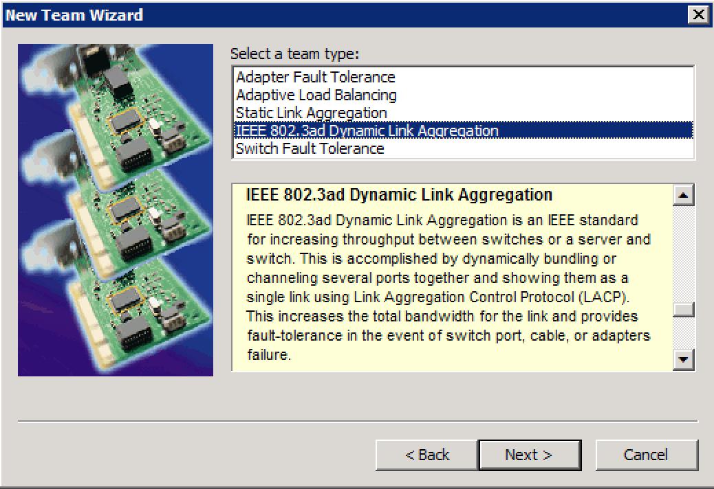
11. Select a profile to apply to the team: Standard Server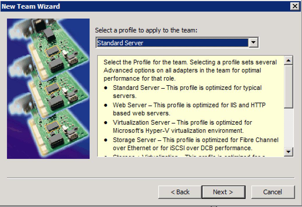
12. Click Finish and allow it to the configure the team.
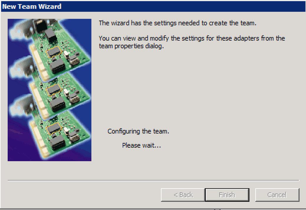
13. Go back to the Intel(R) Ethernet Controller X540-AT2 Properties and select the Teaming Tab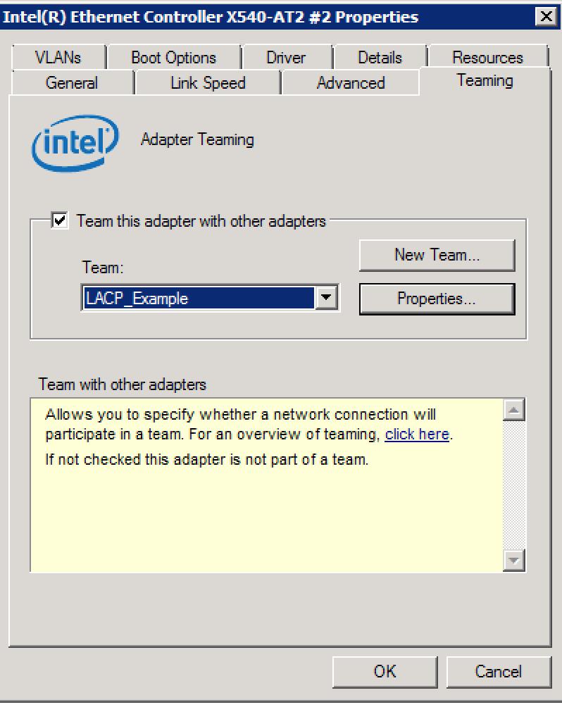
14. Go to Properties
15. In the Team LACP_Example Properties, go to the Settings tab.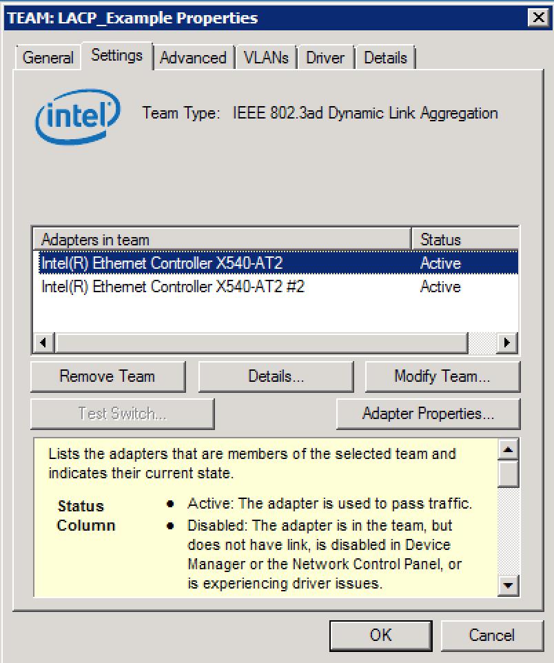
16. Validate that both 10Gb ports are Active as the screenshot above.
17. Open Network and Sharing [Control Panel\All Control Panel Items\Network and Sharing Center] and go back to Change adapter settings.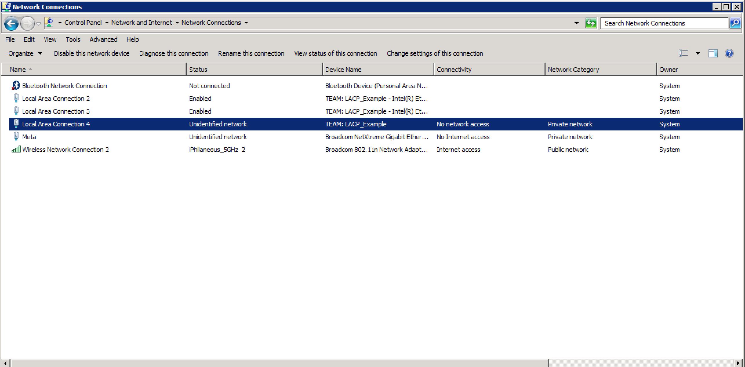
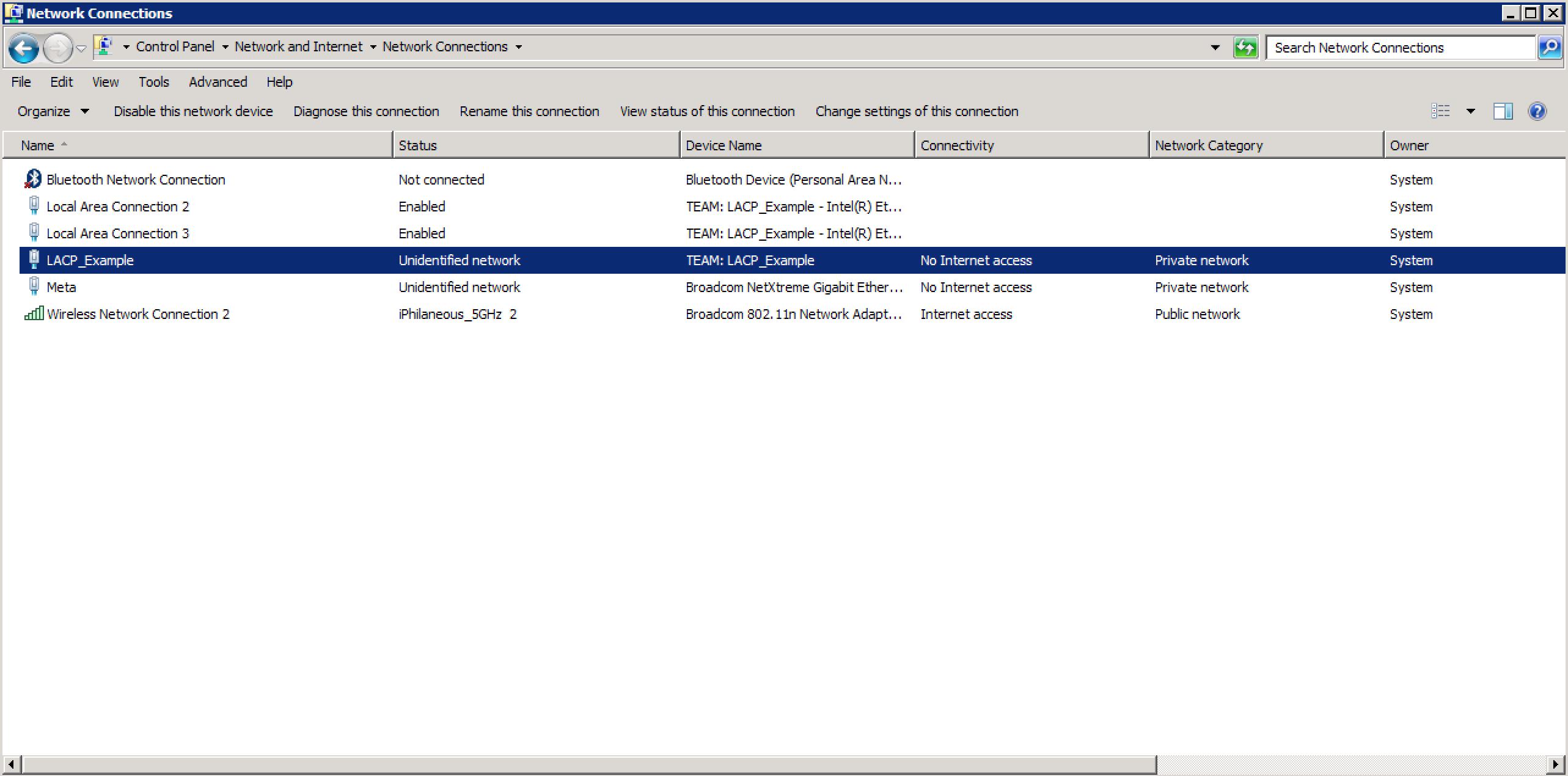
18. Depending on how your Windows Networking is configured (Public and Private), you will see a new Local Area Connection listed. (In this configuration, Local Connection 4 appeared under the Work Network due to the Local Policies set on this machine)
19. To validate the team configuration, click on Local Area Connection 4 (Or the number assigned to your connection)
You should see an aggregate of 20Gbps for the connection. The link speed is listed as 20 Gbps which signifies that (2) x 10Gb Ethernet ports are actually teamed together.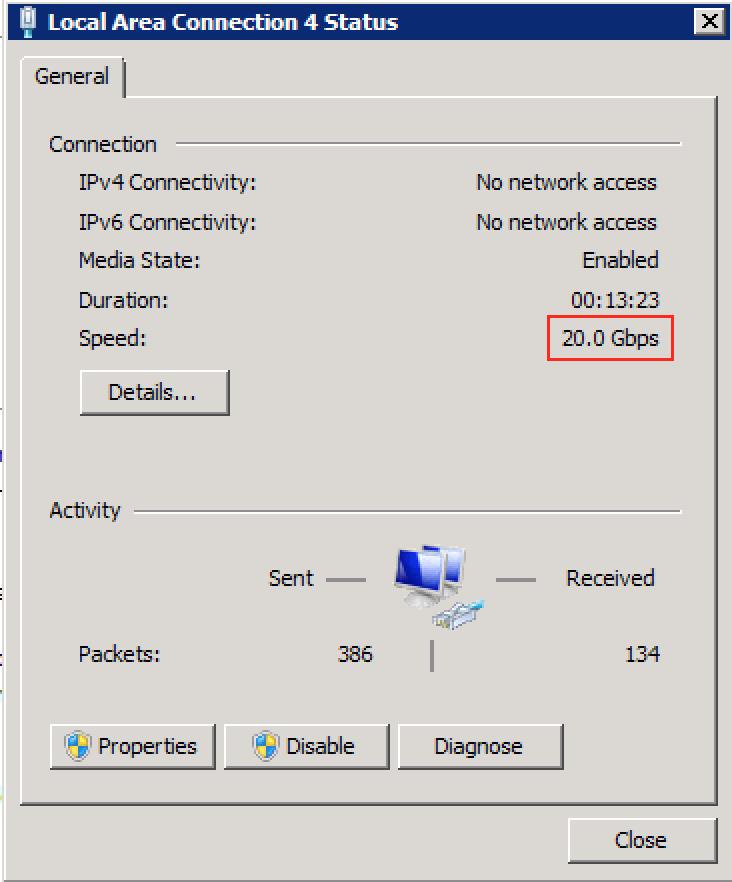
20. Click Properties. You can also verify in this dialogue that it is Connecting Using: TEAM: LACP_Example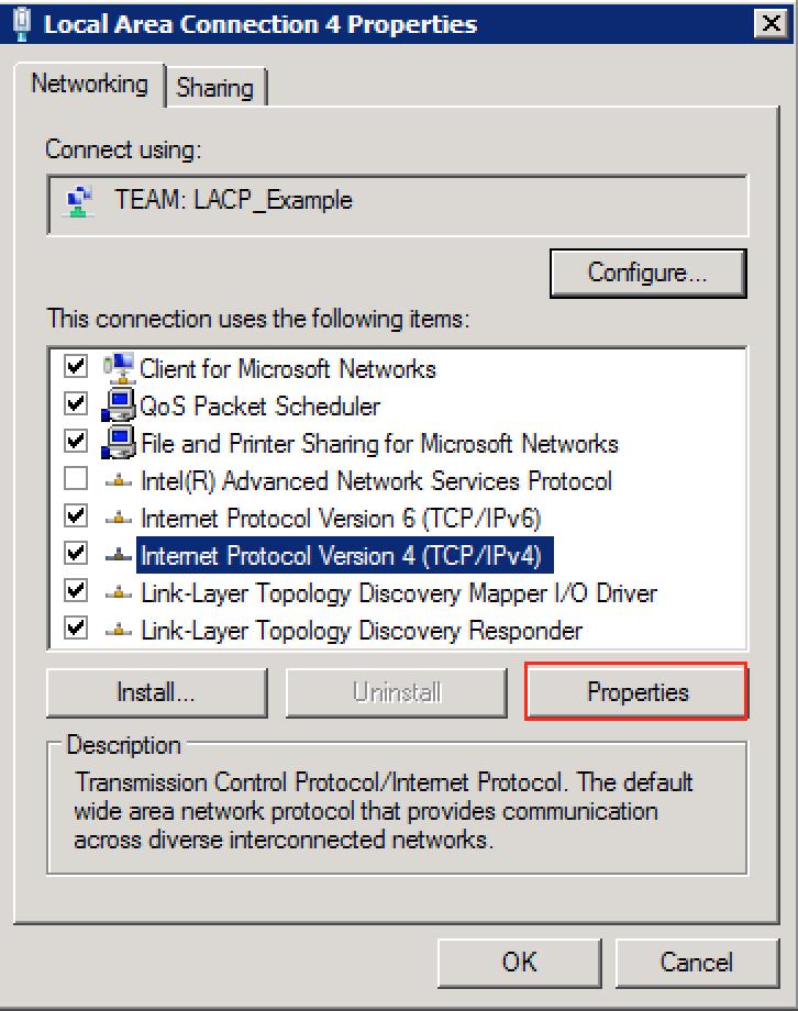
21. Select IPv4 (Double-Click) or click on Properties.
22. In this example, I'm configuring a static IP. Click OK to Save.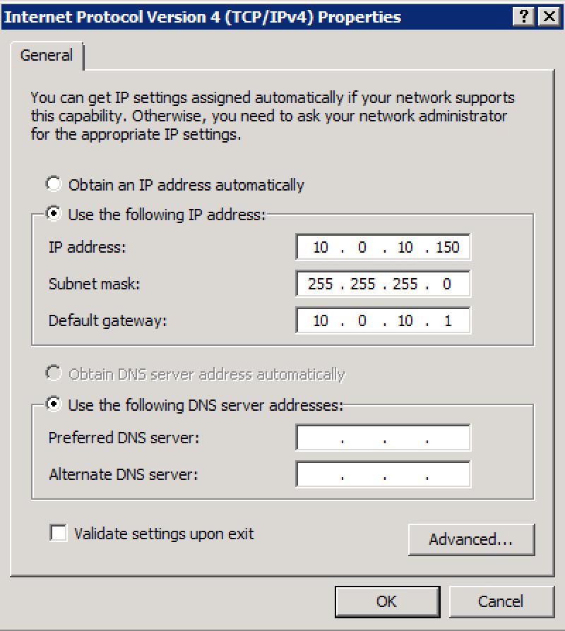
23. Make sure to ping other devices on the same network to test your connection to your Network Switch.
24. You may also rename the connection. Go to Change adapter settings and right click Rename on Local Area Connection 4
25. Rename the connection with a unique identifiable name of your choice.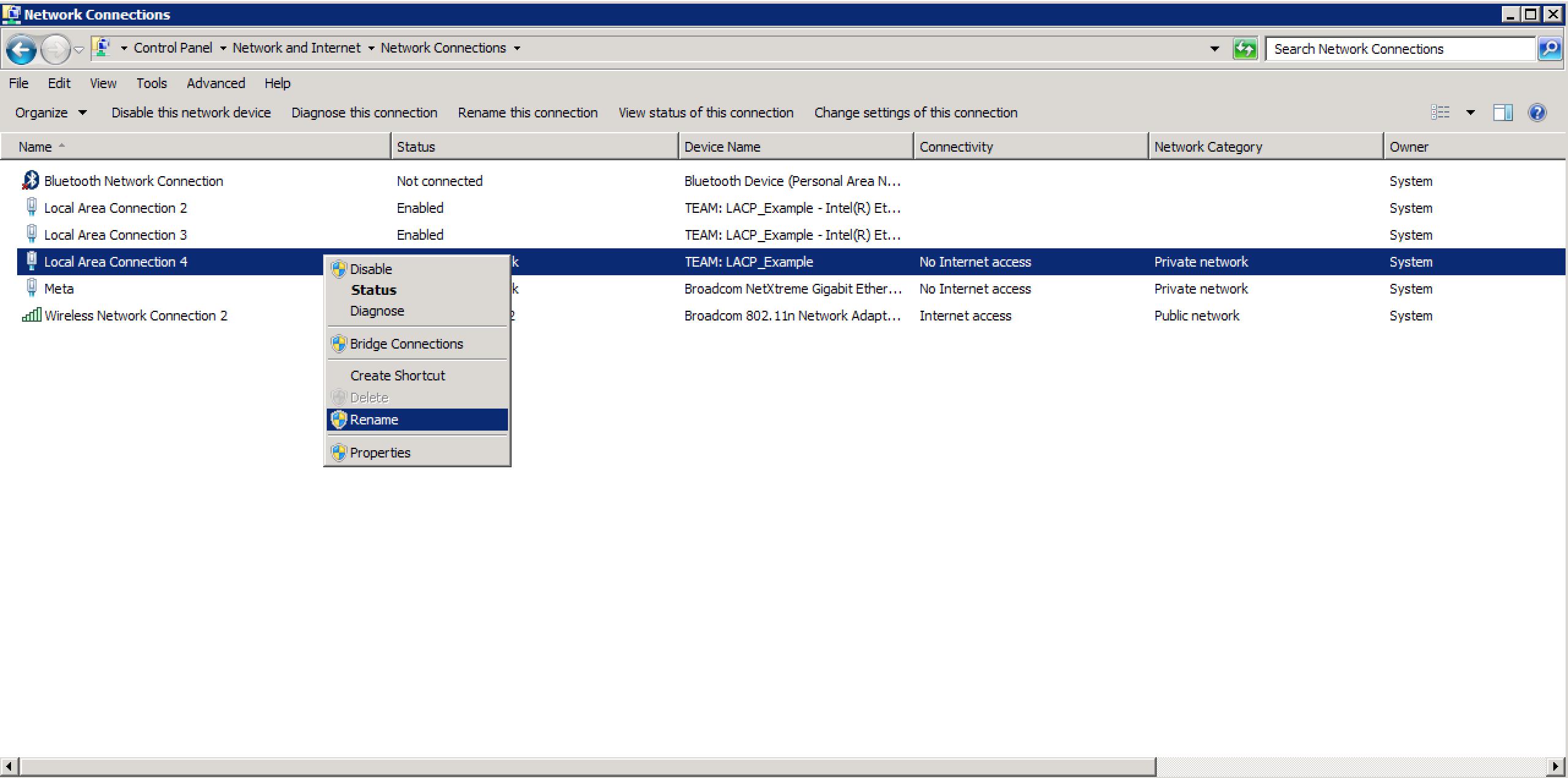
II. Enable Jumbo Frames on Windows WHQL certified driver for Windows 7 SP1 / Windows 8.1 and Windows 10. (All 64bit ONLY)
Enable Jumbo Frames only if devices across the network support them and are configured to use the same frame size. When setting up Jumbo Frames on other network devices, be aware that different network devices calculate Jumbo Frame sizes differently. Some devices include the header information in the frame size while others do not.
1. To verify the current MTU set on the Ethernet Port Team, open Command Prompt and type the following:netsh interface ipv4 show subinterfaces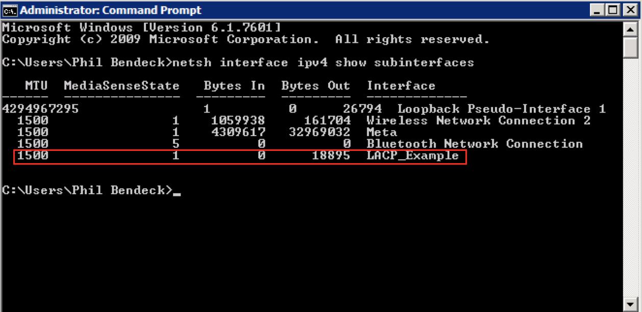
2. In this example, we see that the configured team interface, LACP_Example has an MTU of 1500 (Default)
3. Open Network and Sharing Center and select your teamed interface (LACP_Example)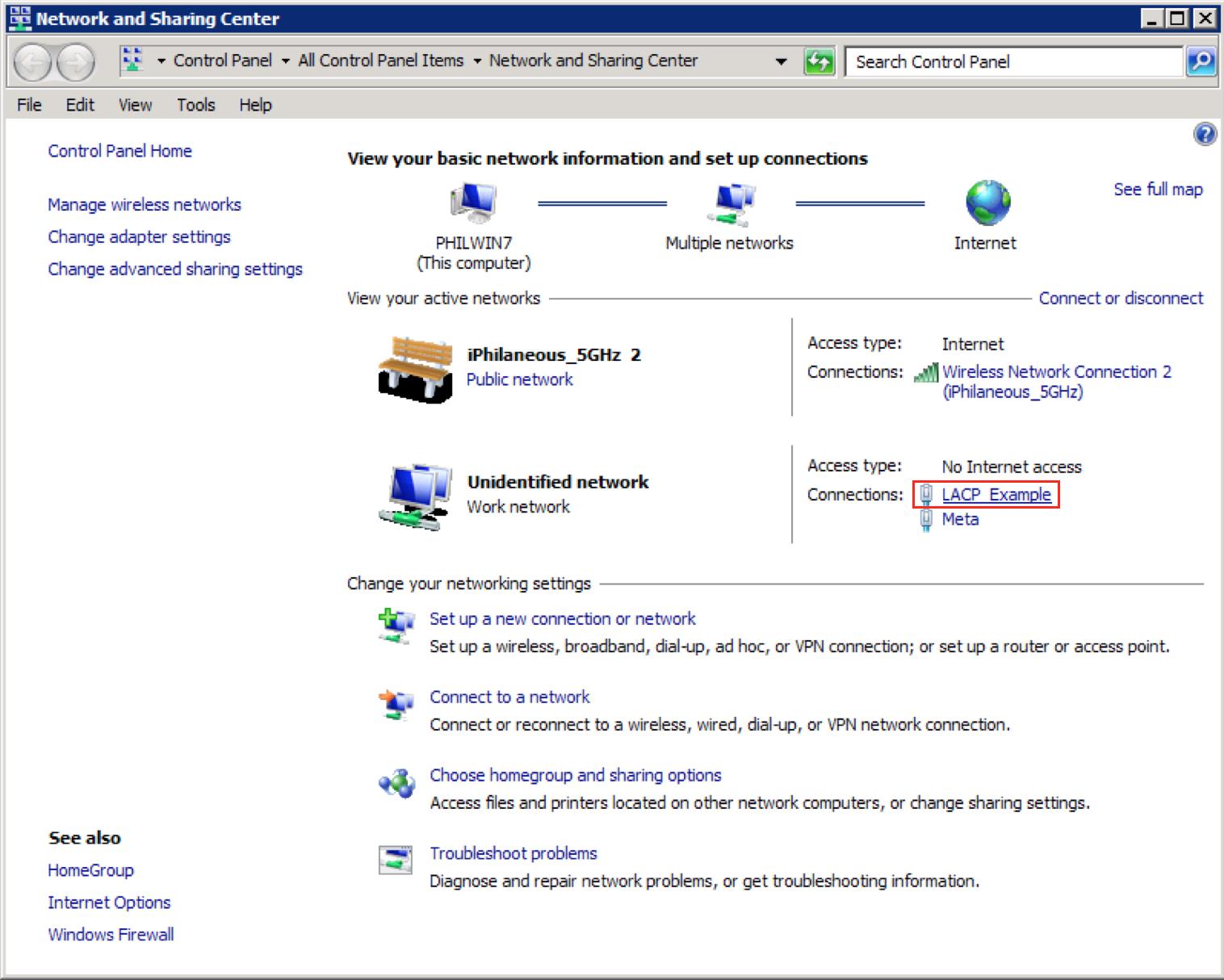
4. Click on Properties and click Configure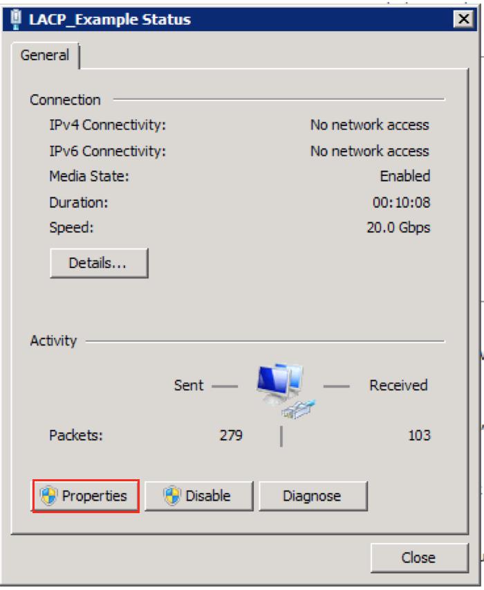
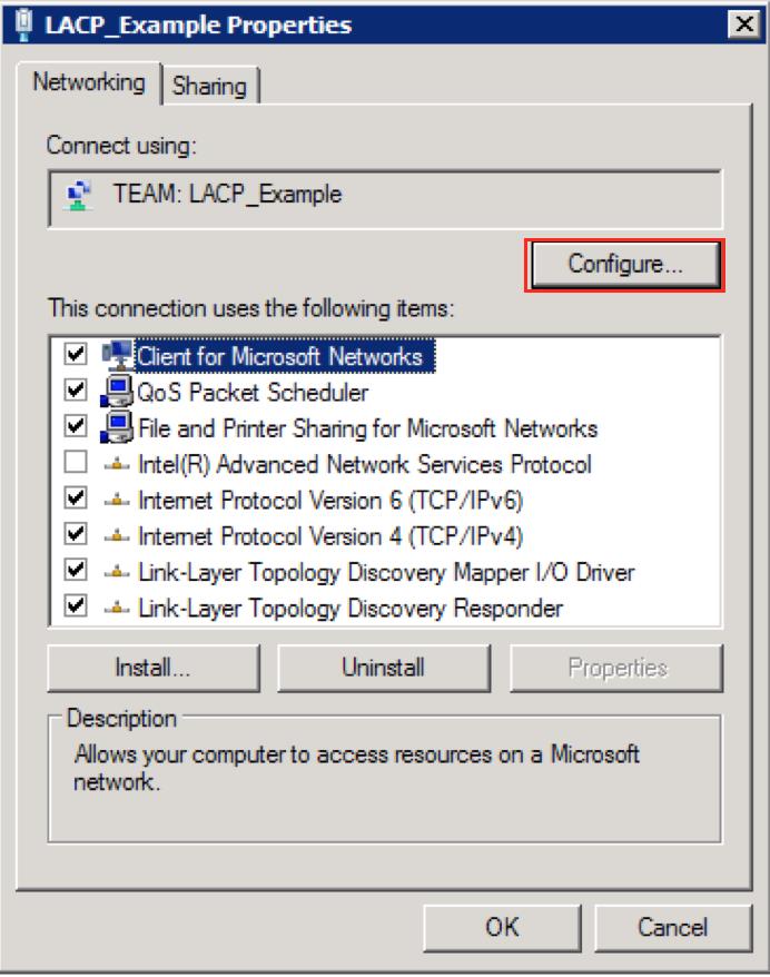
5. Go to the Settings tab and select one of the Adapters in the the team.
6. Click on Adapter Properties.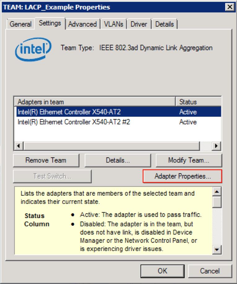
7. Go to the Advanced tab and locate Jumbo Packet.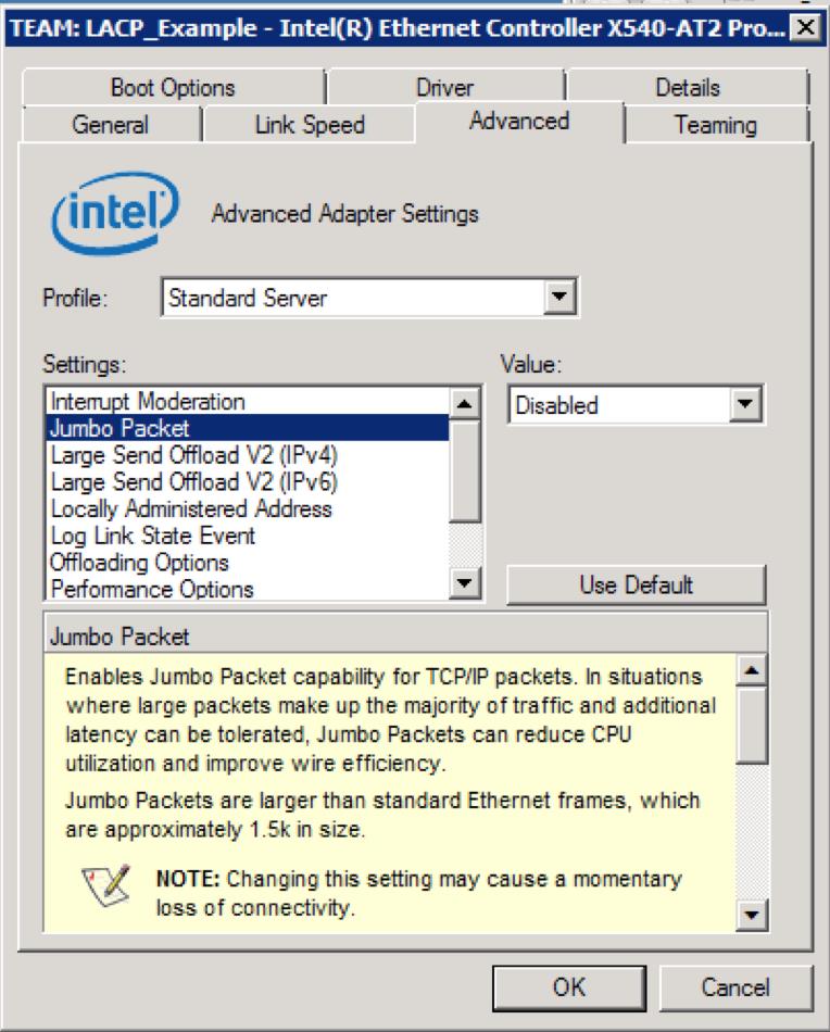
8. Change the Value to 9014 Bytes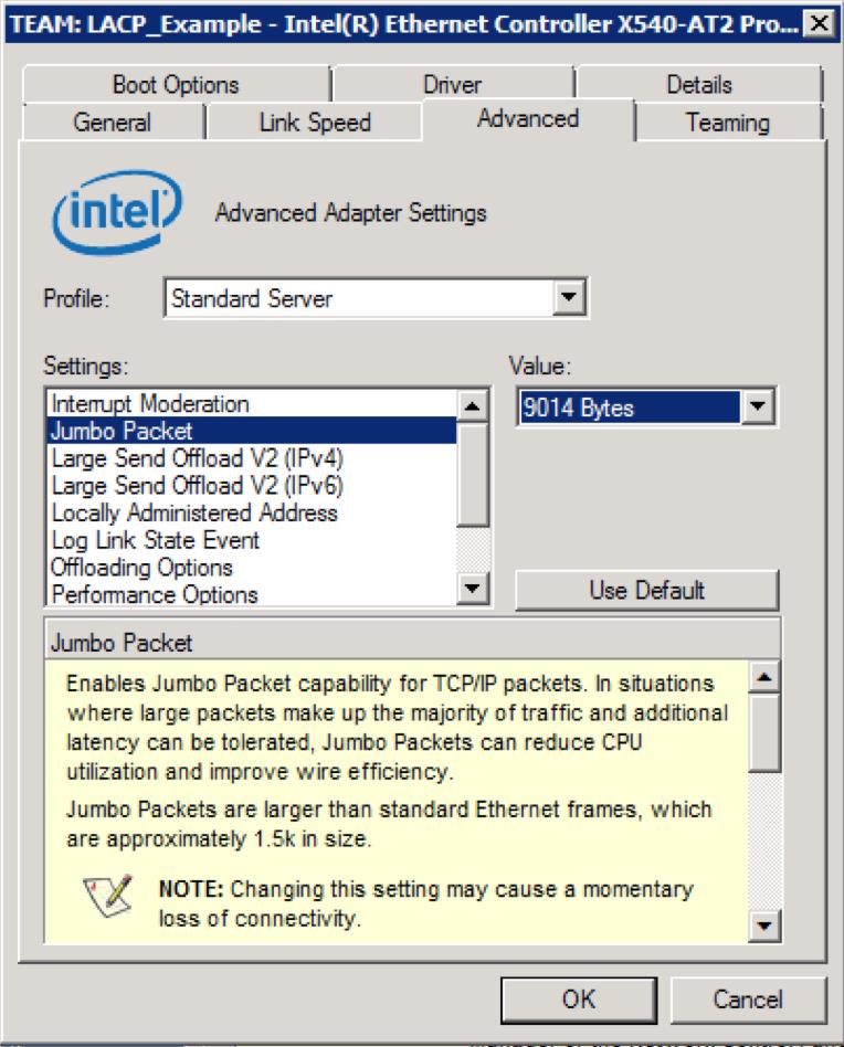
9. Click OK.
10. You will receive a dialogue that states:
"All devices in a team must have the same value for Jumbo Frames/Jumbo Packets. The Jumbo Frames/Jumbo Packets setting for devices in this team will be changed automatically."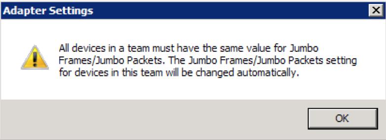
11. Click OK and you will be presented with another dialogue:
"The team will lose connectivity momentarily. Do you want to continue?" Click Yes
12. Allow the teamed interface to reconfigure itself and assign the newly MTU of 9000.
13. Open Command Prompt:netsh interface ipv4 show subinterfaces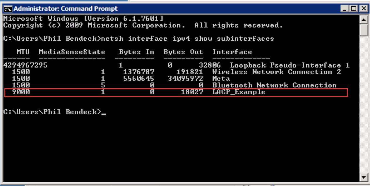
Now you have verified that the teamed interface now has an MTU of 9000.
Note: These changes are revertible.
Advanced Settings for Intel® Ethernet Adapters
III. Create LACP with Default MTU 1500 - OS X
1. Identify the location for each 10Gb Port by opening Network Utility
Network Utility Location = /System/Library/CoreServices/Applications/Network\ Utility.app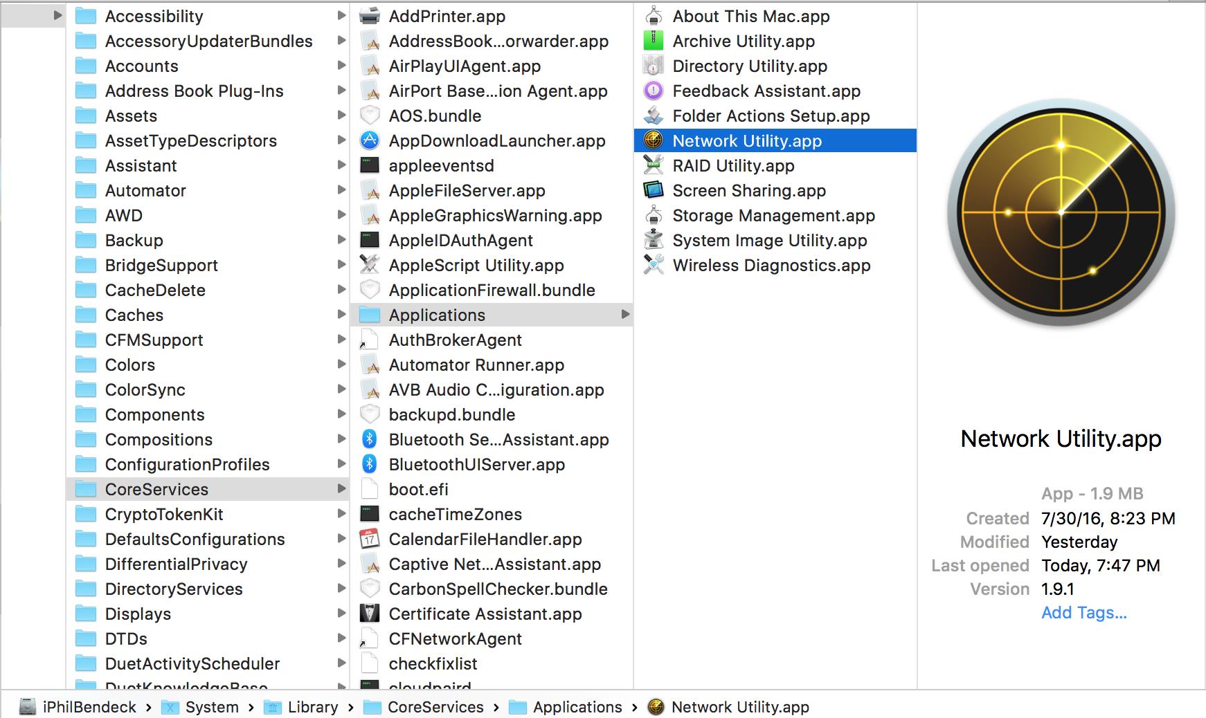
You can also Spotlight Search for it as well.
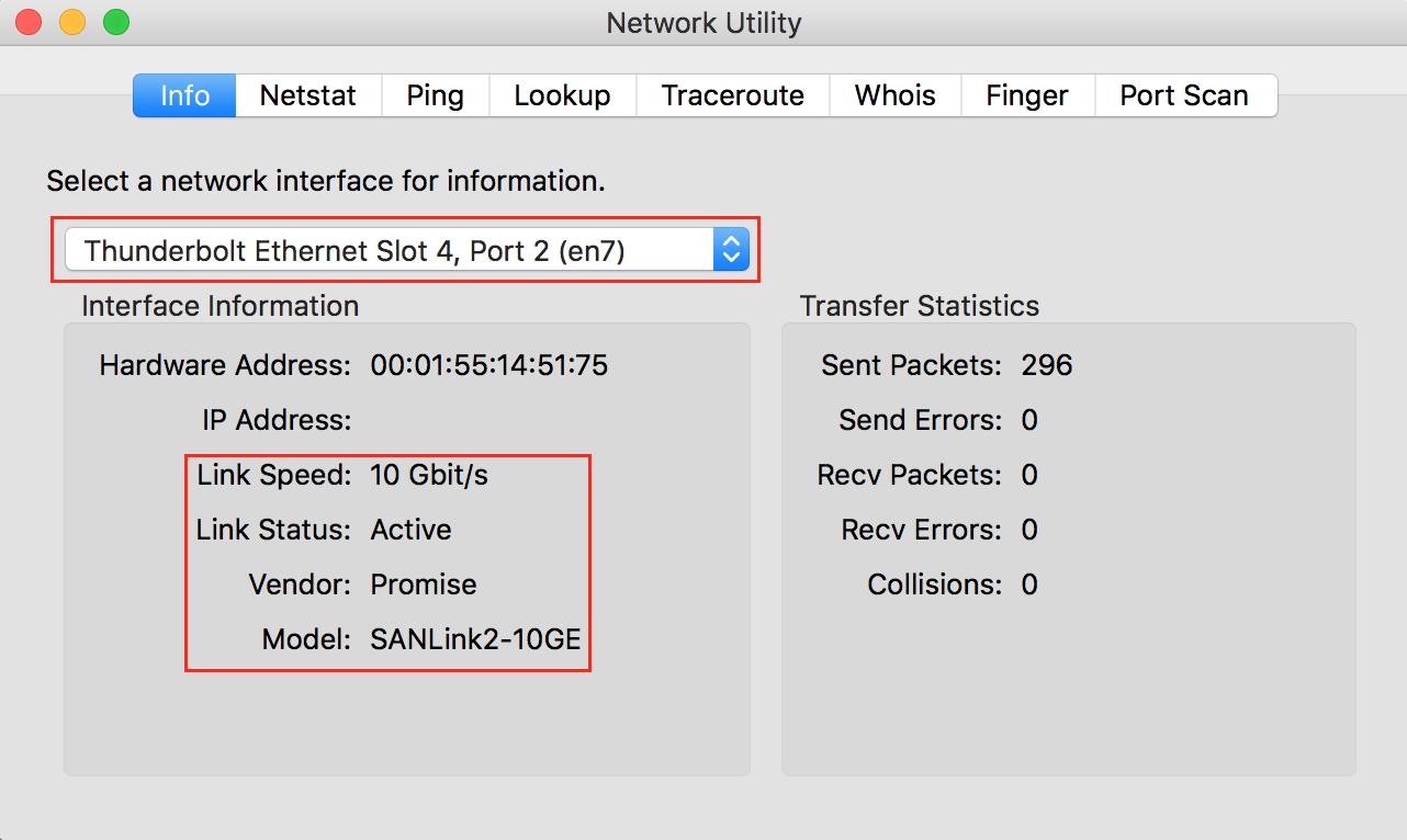
2. Locate each 10Gb interface location: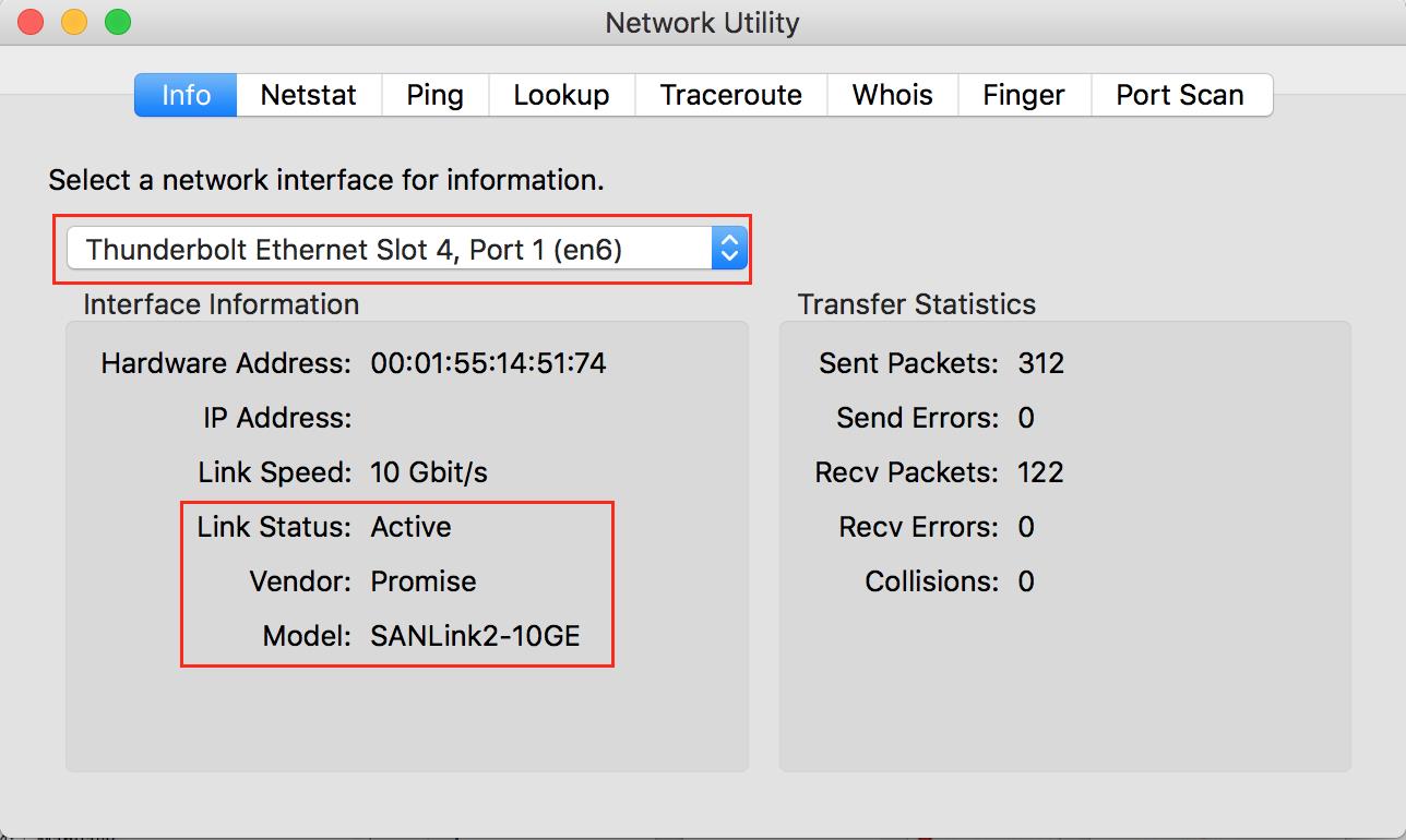
3. Open System Preferences
> System Preferences > Network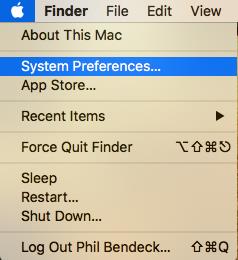
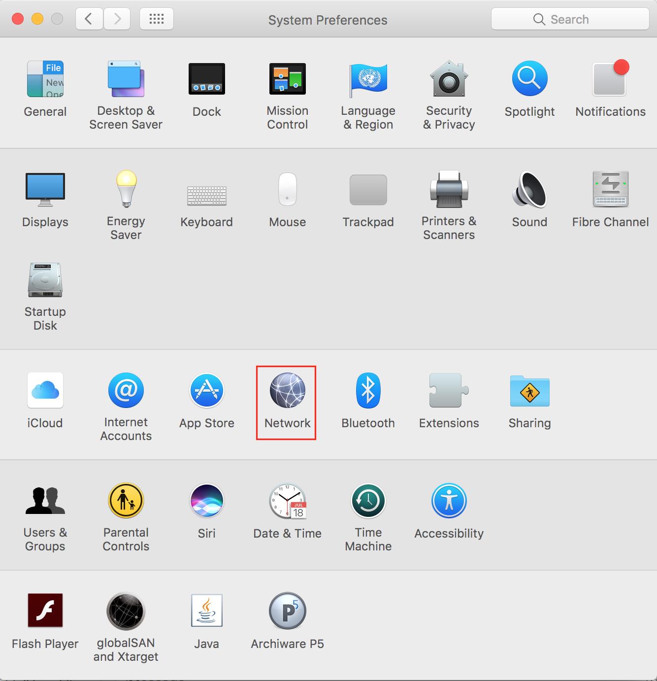
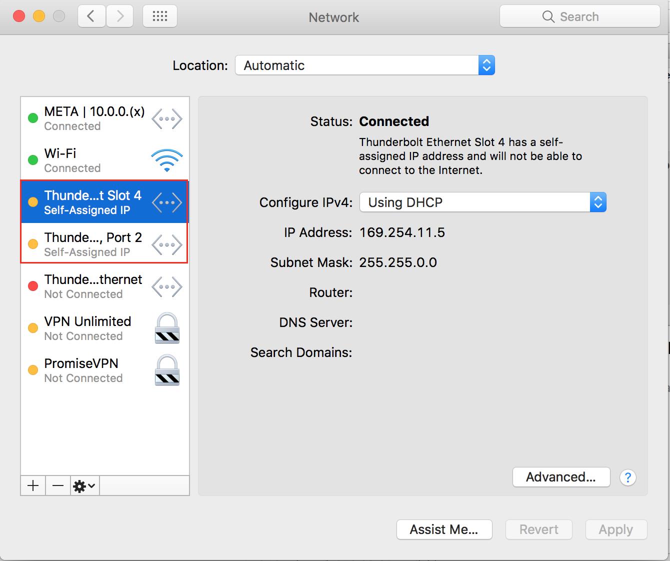
4. Click the Gear button to access the Menu
5. Select Manage Virtual Interfaces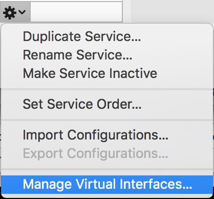
6. Click on the + symbol and select New Link Aggregate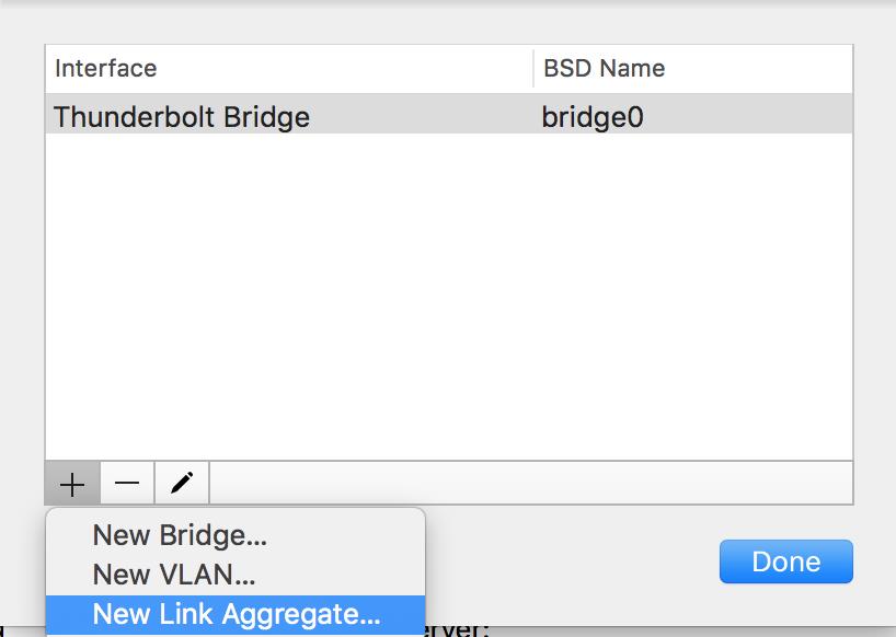
7. Enter the Aggregate Name and select both 10Gb Thunderbolt Ethernet Ports.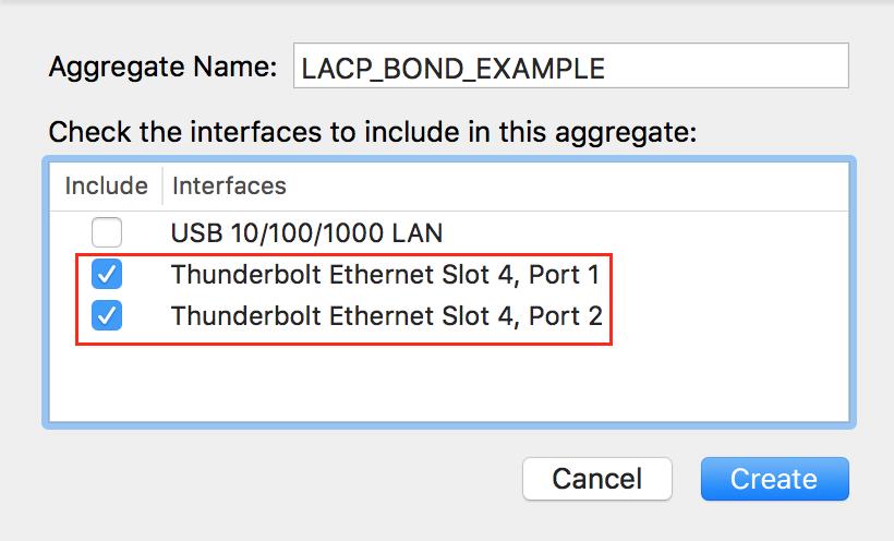
8. Click Create.
9. LACP_BOND_EXAMPLE has now been assigned to BSD Name bond0. Click Done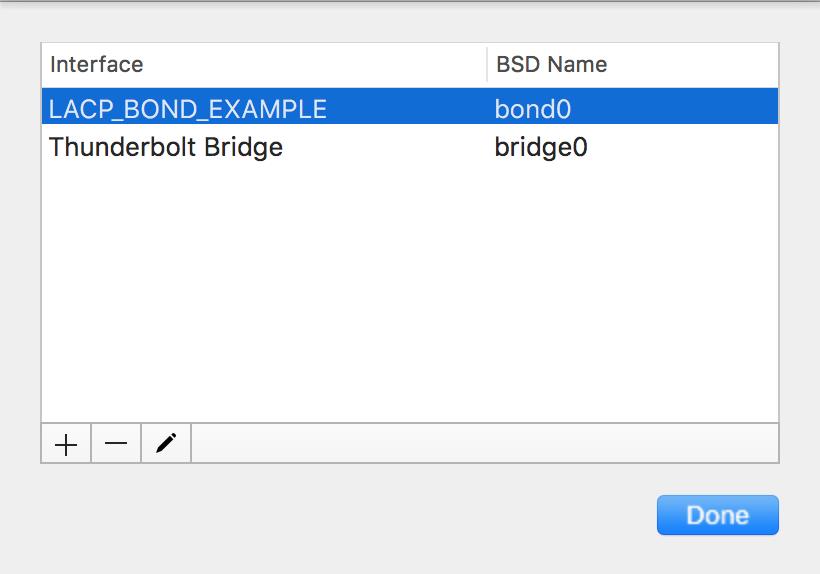
10. Click Apply to Save the Changes.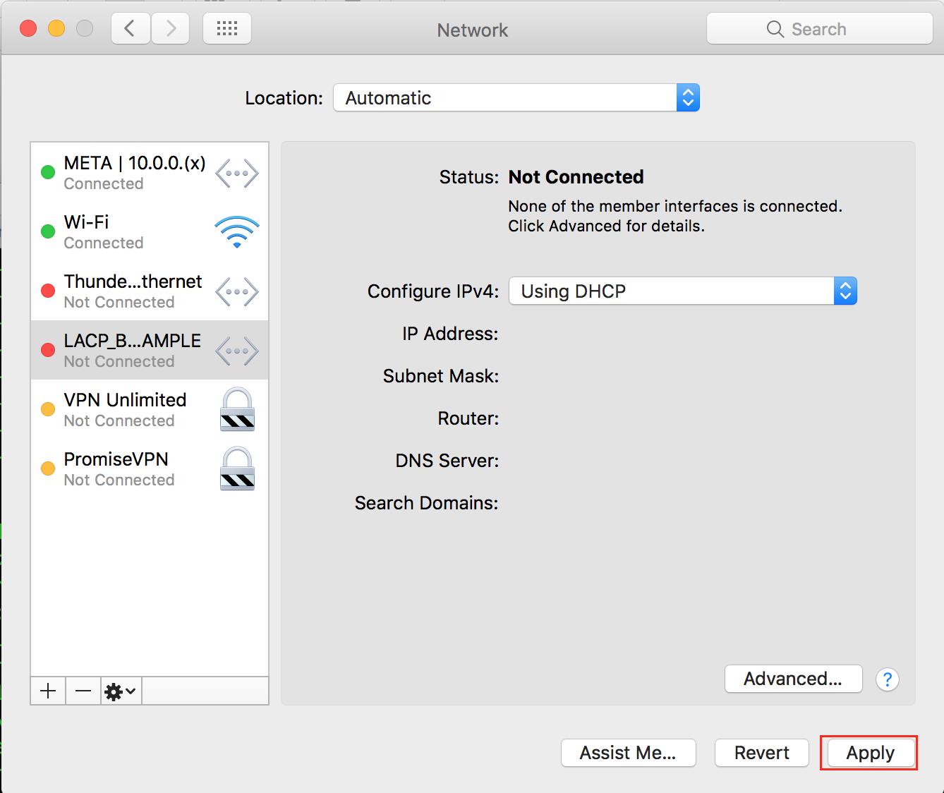
11. Now the LACP bond will have a yellow indicator after you click Apply. In this example, the bond configured itself with an IP Address of 169.254.67.24 with a class B subnet mask of 255.255.0.0. This will happen by default when there is no DHCP server and the client uses the self-configured IP address. All you need to do is assign the correct IP address and subnet mask that corresponds to your 10Gb network.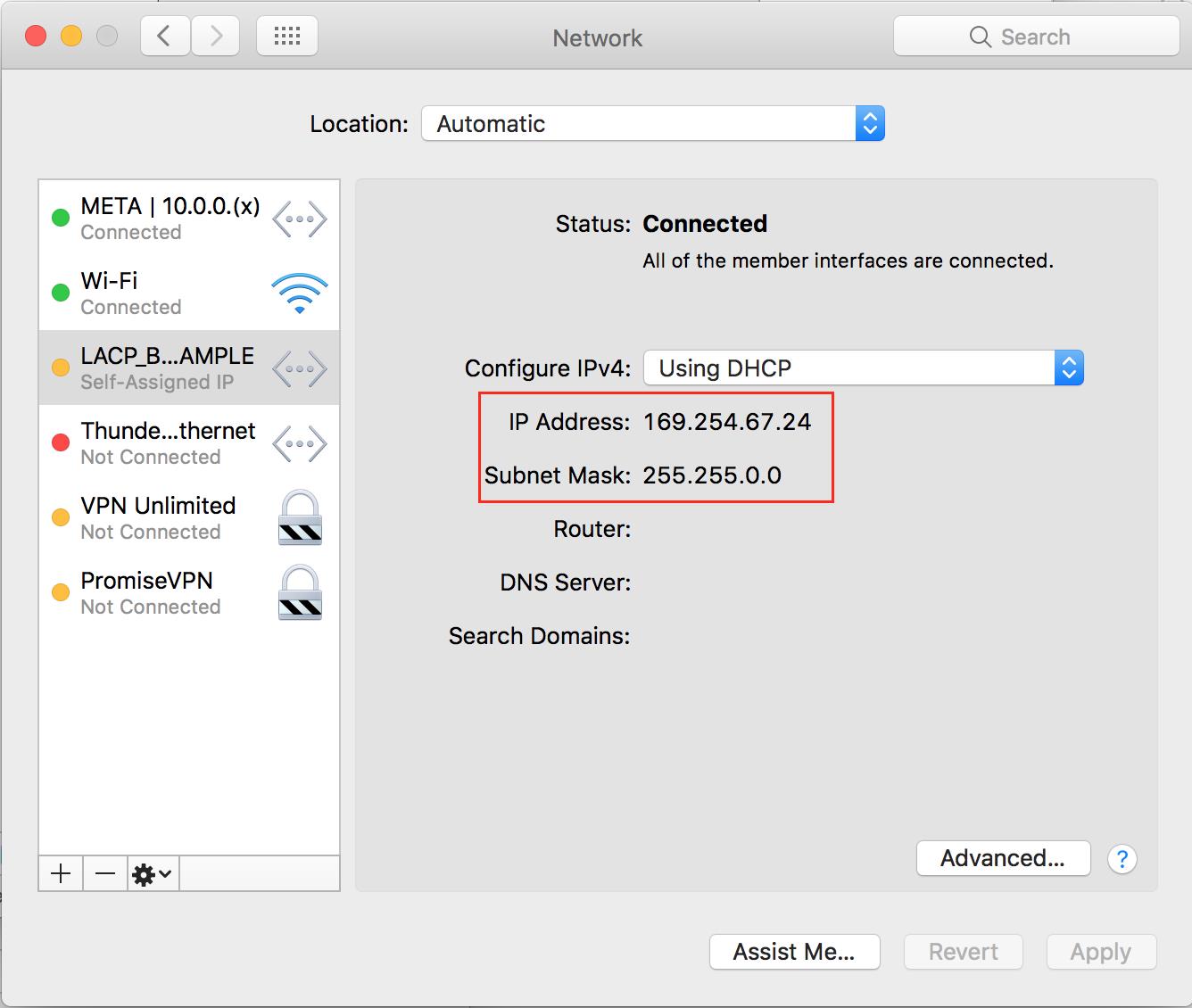
12. Before changing the IP address on the LACP bond, check to make sure both 10Gb ports are active. Go to Advanced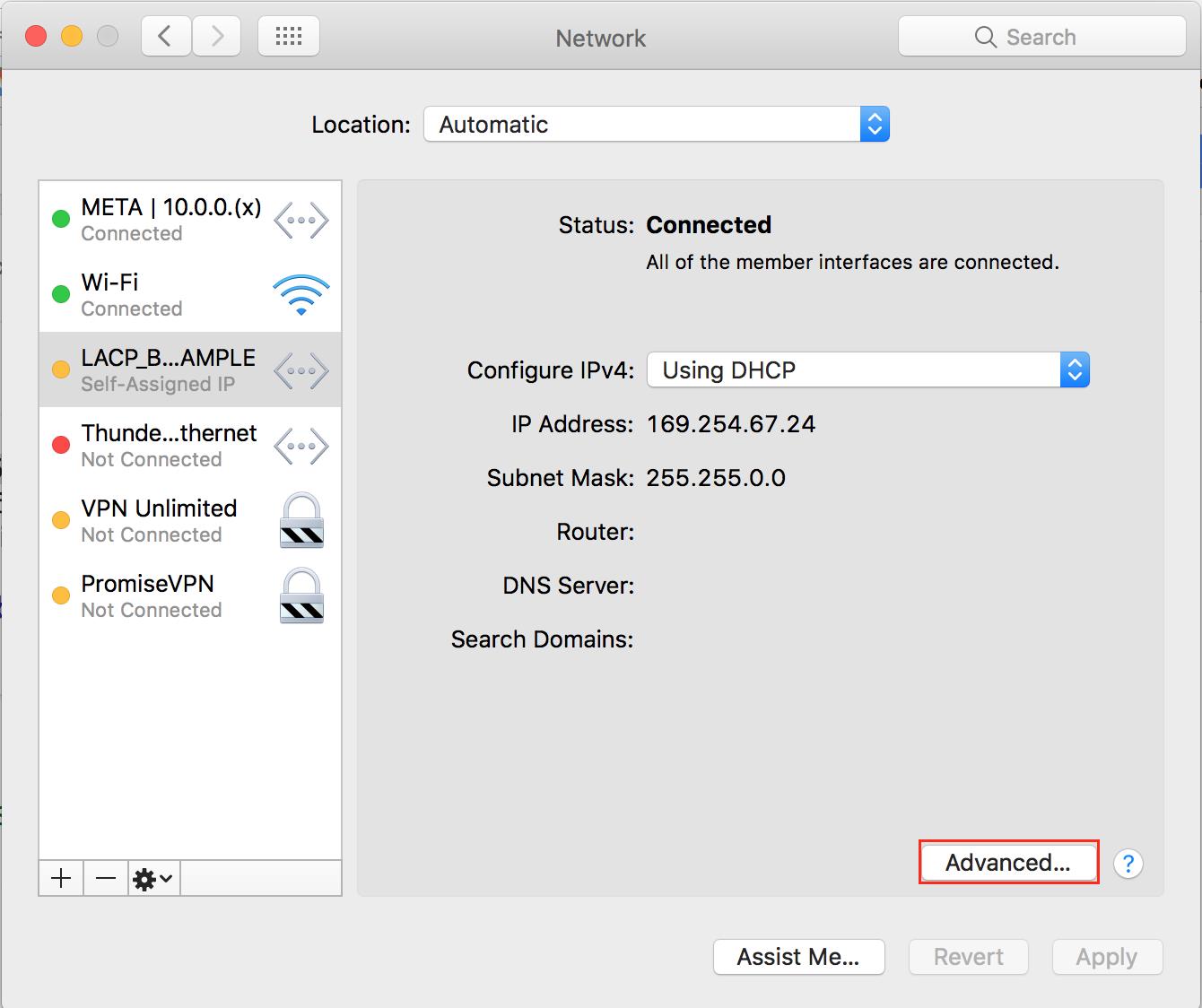
13. Verify the both ports in the Bond Status tab are both active (Sending/Receiving) and have an OK status.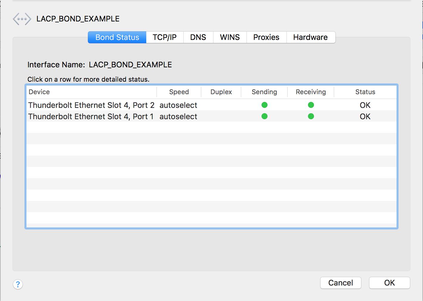
14. Click OK to exit.
15. If you will be configuring a static IP Address, Configure IPv4 Manually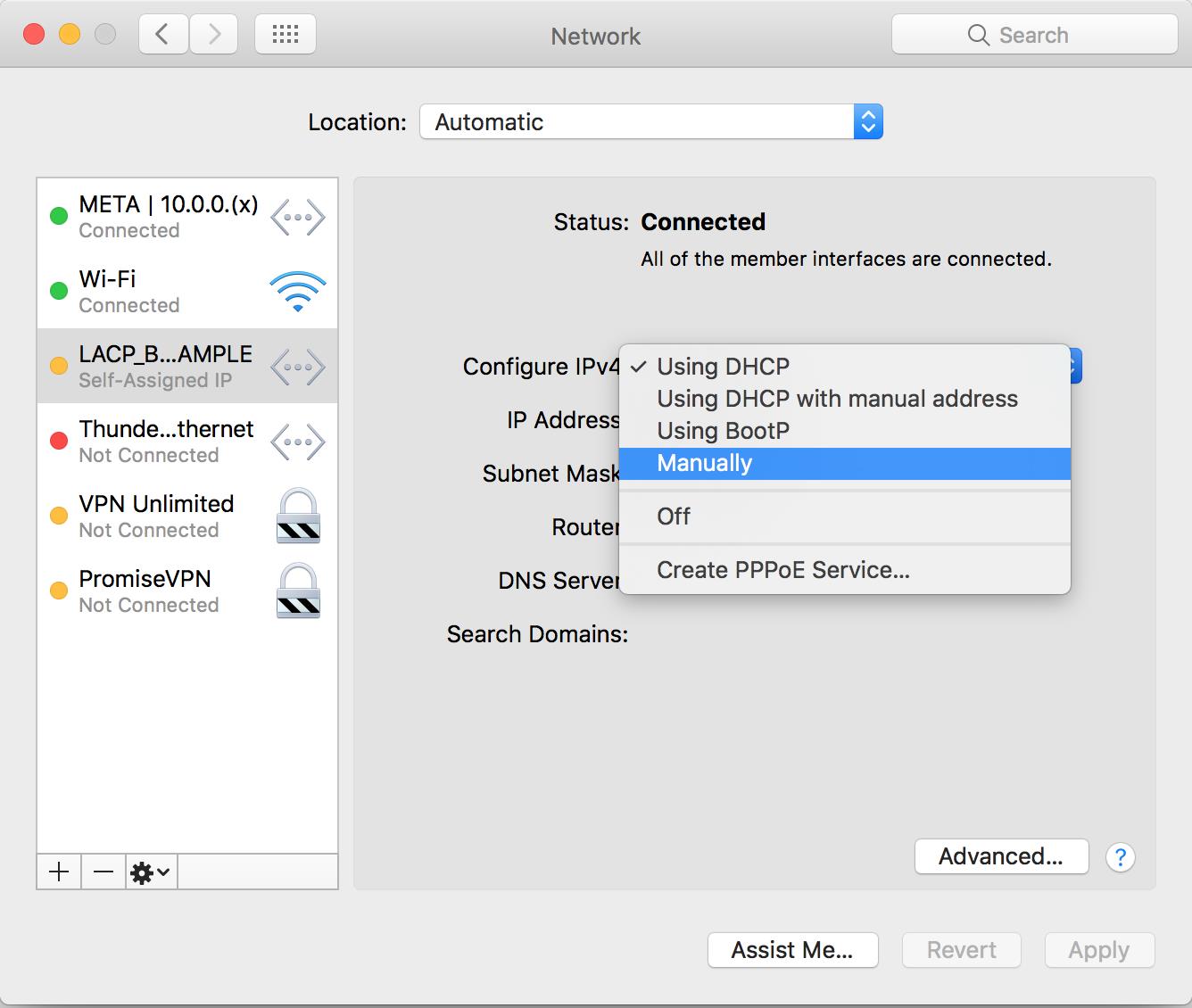
16. After assigning the IP Address and subnet mask on the LACP bond, click Apply. The indicator status light will turn to green after you click Apply.
(I'm not using a Router IP Address in this example)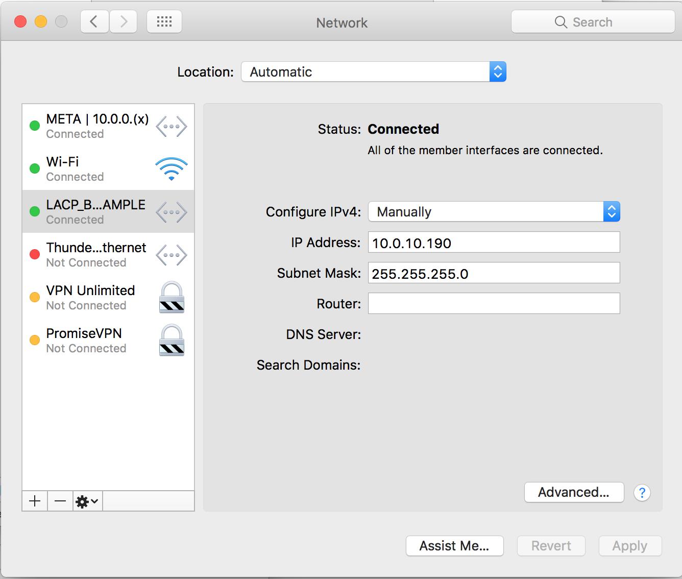
17. Verify the MTU by going back to Advanced and under the Hardware tab. The configuration is set to Automatically; therefore, it will negotiate at the MTU packet size that the switch is configured to transmit.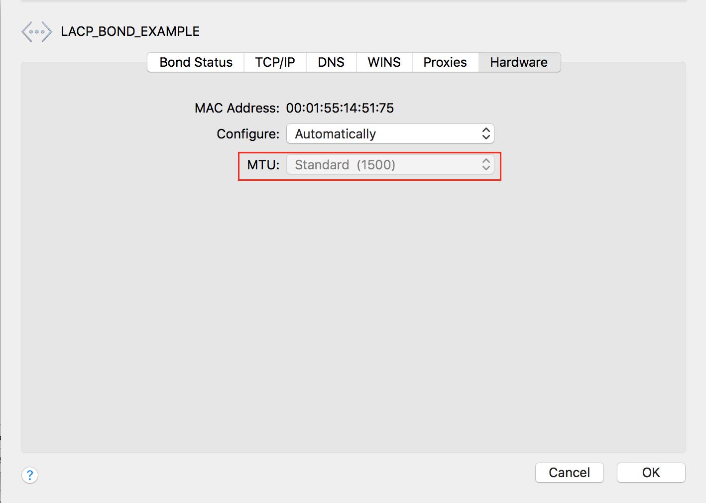
18. You can also verify the same in the Terminal with the following command:
ifconfig bond(x) = x being the number assigned to the bond.
In this example:
ifconfig bond019. Verifying the MTU with the SANLink Utility
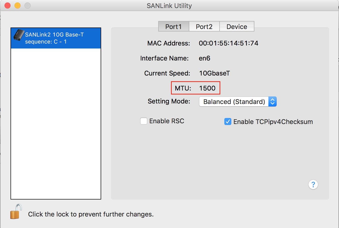
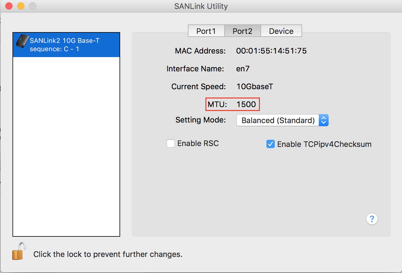
Note: RSC (Receive Side Coalescing) will be enabled by default, if your Network is configured on a Tagged VLAN, you may see an increase in performance by disabling it. It has also been documented in our previous SR 2.6 Release Notes.
Download Release Notes SR 2.6
IV. Enable Jumbo Frames MTU 9000 - OS X
1. In Network Preferences, select your LACP bond (LACP_BOND_EXAMPLE)
2. Click Advanced and locate the Hardware Tab
3. Change Configure from Automatically to Manually
4. Change the MTU to Jumbo (9000) and click OK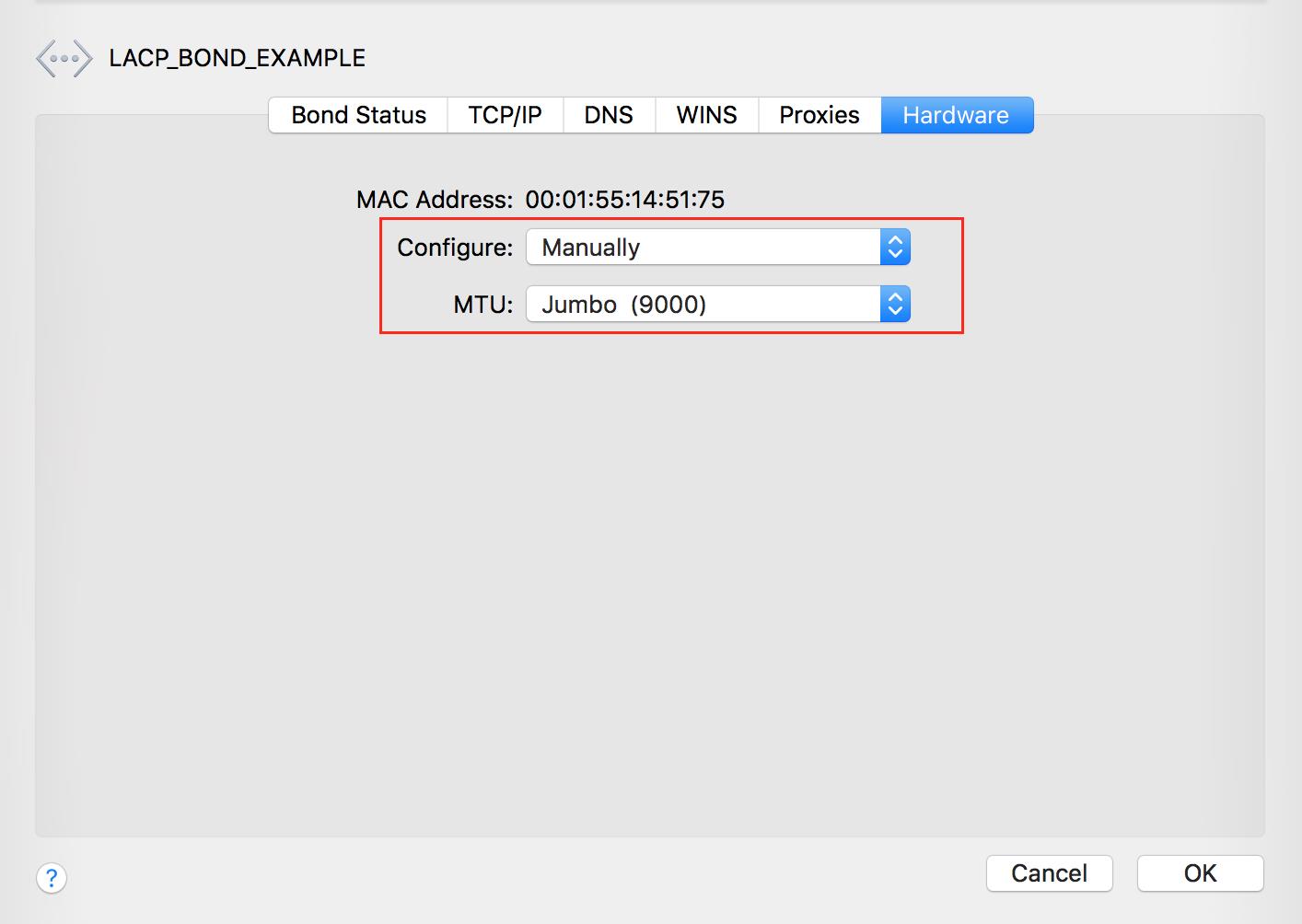
5. Click Apply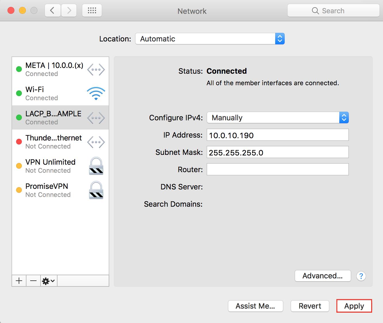
6. Verify the MTU change via Terminal.
ifconfig bond(x) = x being the number assigned to the bond.
In this example:
ifconfig bond07. Verifying the MTU with the SANLink Utility
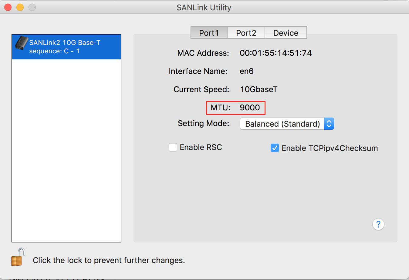
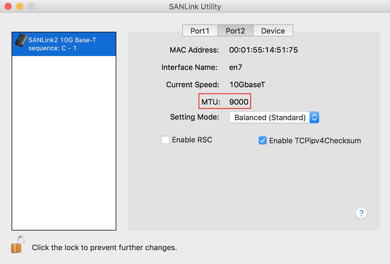
If you have any questions or concerns, please open a support request via https://support.promise.com

