The SAS expansion cable is the weakest link in an otherwise cable-less system, and issues can arise due to a faulty cable having a marginal signal that will only cause a transmission problem under very particular circumstances. A SAS cable has a fragile connector inside that could be affected by all of the handling it undergoes from manufacturing to final installation, so care must be taken when unpacking and connecting the cables between the VTrak enclosures.
The Promise VTrak has the ability to report any signal errors that may occur over the two SAS paths from the RAID controllers to the JBOD I/O modules. This can be done by using the serial port and a terminal emulator or using the network port and a telnet or SSH session.
The command to display SAS communication error statistics is:
administrator@cli> sasdiag -a errorlog -l expander -e X -i Y
The two command parameters used to check the individual SAS ports of each RAID controller and I/O module are:
- -e which refers to the enclosure number, starting with 1, the RAID unit.
- -i which refers to the expander number, 1 on the left and 2 on the right.
This diagram illustrates the values of these two parameters and the SAS ports they are referencing, which can be best thought of as rows and columns.
Note: additional JBODs would be numbered 3, 4, etc.
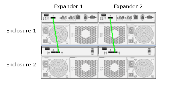
For this example, we have one VTrak RAID and one VTrak JBOD, which gives a total of four SAS ports to check.
To display the SAS statistics for the RAID controller on the left we would issue the command:
administrator@cli> sasdiag -a errorlog -l expander -e 1 -i 1
To display the SAS statistics for the JBOD I/O module on the right we would issue the command:
administrator@cli> sasdiag -a errorlog -l expander -e 2 -i 2
This command will return the SAS statistics for each “lane” - denoted by the PHYId - with the first sixteen entries being for the 16 drives in the enclosure, and the remaining eight entries for the SAS expansion port. This means that even though 24 entries are returned, we will only be looking at entries 17 through 24.
administrator@cli> sasdiag -a errorlog -l expander -e 1 -i 1
EnclosureId: 1 ExpanderId: 1
SASAddress: 50-00-15-5d-23-d4-72-3f NumOfPHY: 24
----------------------------------------------------------------------------
PHYId: 1 InvalidDwordCount: 0
RunningDisparityErrCount: 0 LossOfDwordSyncCount: 0
PHYResetProblemCount: 0 DriveFlatId: 1
SlotNumber: 1 IsConnectedtoExtPort: No
ConnectorID: N/A
.
.
.
----------------------------------------------------------------------------
PHYId: 17 InvalidDwordCount: 0
RunningDisparityErrCount: 0 LossOfDwordSyncCount: 0
PHYResetProblemCount: 0 DriveFlatId: 257
SlotNumber: 0 IsConnectedtoExtPort: No
ConnectorID: N/A
----------------------------------------------------------------------------
PHYId: 24 InvalidDwordCount: 0
RunningDisparityErrCount: 0 LossOfDwordSyncCount: 0
PHYResetProblemCount: 0 DriveFlatId: 1
SlotNumber: 1 IsConnectedtoExtPort: No
ConnectorID: N/A
The error counts we want to examine are:
InvalidDwordCount
RunningDisparityErrCount
LossOfDwordSyncCount
They should all be “0” if there are no transmission errors detected on the port.
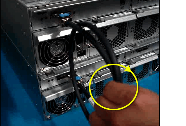
To test the quality of the SAS expansion cable and attempt to induce any errors that may occur due to a marginal cable, we will perform what is referred to as a “wiggle” test. This involves holding the cable near the center and slowly moving it in a circle approximately two to three inches in diameter for a few seconds. Please see the attached video.
Use the sasdiag command again to display the SAS statistics for the two SAS ports that are connected by the SAS cable under test:
administrator@cli> sasdiag -a errorlog -l expander -e 1 -i 1
administrator@cli> sasdiag -a errorlog -l expander -e 2 -i 1
If any SAS errors occur, the counts for PHYIds 17 through 24 could increase.
----------------------------------------------------------------------------
PHYId: 17 InvalidDwordCount: 127
RunningDisparityErrCount: 11 LossOfDwordSyncCount: 5
PHYResetProblemCount: 0 DriveFlatId: 257
SlotNumber: 0 IsConnectedtoExtPort: No
ConnectorID: N/A
If the test results in these counts increasing, power down both the RAID head and attached JBODs and then unplug and re-insert the SAS cable(s). Power back up and re-run the test. If the counts continue to increase, replace the SAS cable and test again.
To make it easier to recognize any incrementing errors, you may want to clear the SAS counters. For a VTrak running firmware SR2.5, the RAID controllers must be restarted. For firmware SR2.6 you can use this command, remembering to run it for each expander:
administrator@cli> sasdiag -a clearerrlog -l expander -e 1 -i 1
Note: the controller restart method must be used for the VTrak for Mac.
Additional Information:
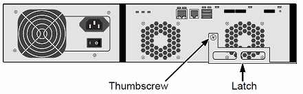
-PHYIds 17-20 signify the "Out" port on the controllers/IO modules. They are identified by the "Circle" on the rear of each module.
-PHYIds 21-24 signify the "In" port on the controllers/IO modules. They are identified by the "Diamond" on the rear of each module.